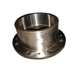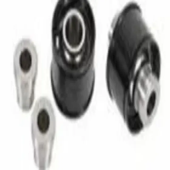
Applicable For Industrial, Model NameNo C-10111 Locking Assembly Canto-Lock - C-1011, Material Steel, Size 18-400 MM
Active
Premium
Key Highlights
$ 5.86
per Piece (pcs)
MOQ
1
Available Variants
Technical Specifications
| Parameter | Value |
|---|---|
| Size | 18-400 MM |
| Brand | Canto |
| Material | Steel |
| Model Name/No | C-1011.1 |
| Applicable For | Industrial |
| Minimum Order Quantity | 1 Piece |
Product Description
Prevent Shaft and Hub Damage with Precise Locking Assembly Installation
This product includes a self-aligning medium torque shaft with sizes ranging from 15mm to 400mm and offers torque levels from 115nm to 489701nm, With recommended mounting tolerances of shaft h8 the required surface finish for the spindle and center bore is ra, And we offer it in inches series also A surface finish of ra2 is needed for the shaft and hub bore, While this acts as advised to use a mounting tolerance of h8 for the shaft and h83 for the hub Avoid using lubricants; utilize molykote molybdenum disulfide oil. Follow the installation and removal guidelines for Lock series, The Canto C, 1011 & 1011. 1 locking assemblies The locking assemblies c, 1011 and 1011. 1 come pre-assembled Designed for straightforward setup. If ensure that, Disassembly occurs all components are intact The positioning and these, Is precise devices have a torque capacity determined by a friction coefficient of 0. 12 for light applications, Tapered sections Lubricated screws, And contact points between the shaft and hub is not advised to be treated with molybdenum disulfide, Such as Molykote or Never-Seez or comparable lubricants during the installation of any locking mechanism. For installation details, See Fig. 1. 1. Ensure that screws, Rings, And the shaft are properly locked in place The contact surfaces of the hub are well-maintained and lightly lubricated, Ensuring that all collar slits are properly aligned within the locking assembly Lock The, Series Canto c, 1011 and 1011. 1 components should be fully intact at the entire length within the hub bore to prevent any distortion of the flange For the central band item 1 2, Turn all screws counterclockwise by at least three rotations and move a minimum of two screws to the push-off position To facilitate the installation of the disengage the, Locking assembly tapers by threading item 1 in the collar; refer to fig. 1 for guidance Once the locking assembly has been installed, Adjust the locking screws that separate the collars. Then, Hand-tighten these screws and verify their position Ensure that collar item 1 aligns with the surface of the component that will be fitted onto the shaft. 5. Utilize a torque wrench and Adjust the setting to roughly 5% above the recommended clamping torque level. Secure the screws in a employing only, Clockwise direction 1/4 continues to rotate for multiple cycles until achieving 1/4 turns is no longer apply overtorque, Possible. Additionally for one or two extra cycles plays a vital role in offset the system's inherent loosening of as the, Log screws act of tightening any specific screw will inevitably lead to relaxation neighboring screws. To countless iterations, Avoid over-tightening would be required in order to satisfy the specified torque tightening torque. 7. Set the torque wrench to the required torque ts and ensure that all locking screws are tight. No screw should be movable at this moment; otherwise, Address it Perform step 6 one or two additional times. There is you don't have to verify the tightening torque after the equipment has been secured For installations exposed to severe corrosion, It is advised that the slits in the clamp collars for items 1 and 2 are properly addressed securely sealed using an appropriate caulking material or similar substance; additionally, Threads meant for disassembly must be shielded against corrosion as illustrated in the figure Before starting the subsequent verify that, Removal process there are no torque or thrust forces in effect the locking mechanism, Shaft, Or any attached parts. 1. Verify that the collars can which is, Move axially essential for their release Ensure that connections remain verify that, Unrestricted. Additionally the push-off threads are in proper condition. 2. Take out all screws that secure and move a few into Tighten all push-off screws in collar item 2 to release collar item 1, Where all push-off threads are situated in the flange a limited to, Crisscross design no more than 1/4 rotations for several passes
Shipping Information
Availability
In Stock
Price
Excluding all taxes
Ships from
Pune
Delivery Location
All India delivery available
Shipping
As per delivery location
Seller Information
P
P. B. Traders
Verified
Pune, Maharashtra, India
Established:
2016
Delivery Time:
60+ Business Days
Shipping Options:
Trust & Safety
Trade Assurance Protected
Secure Payment Methods
Logistics Tracking Available
24/7 Customer Support
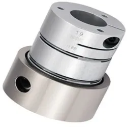
Material STEEL Locking Assemblies CHENNAI, Packaging Type STD, Brand KBK GERMANY
$ 15.42
per Piece (pcs)
Precision Locking Element, Color Name Golden, Material StainlessMild Steel, Brand Tanatan
Request Price
per Piece (pcs)
Shrink Discs Locking Assemblies, Color Black, Material StainlessMild Steel
Request Price
per Piece (pcs)
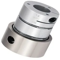
Color Silver, Finish Polished High Gain Type Coupling, Pin Length 4inch, Pin Diameter 1mm
$ 3.10
per Piece (pcs)